All industrial and engineering projects involve a variety of materials and parts. Piping systems, for example, require interior flanges or connecting parts to enhance fluidity and prevent leaks.
It is important to choose the right flange for the right job. Highly resistant plastic flanges exist, for instance, which are often used to fix electrical wires and their installations in place.
However, the type used for piping systems are forged flanges made in a variety of metals.
This said, in this post we tell you everything you need to know about flanges, explaining what they are, what they are used for, their different types, and much more.
What are flanges?
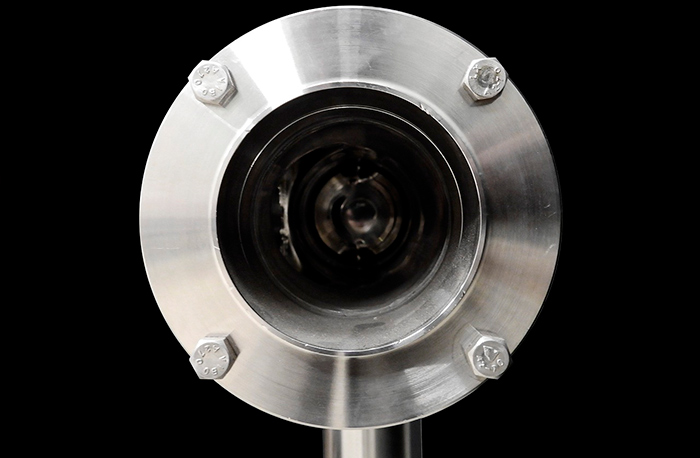
Flanges are connecting elements used in piping and boiler work. They come in ring, disc or collar shapes and are fitted to a pipe either to connect it to other pipes, valves, etc., or to block off a section of the pipe.
Flanges also make it easy to separate pipe connections when required.
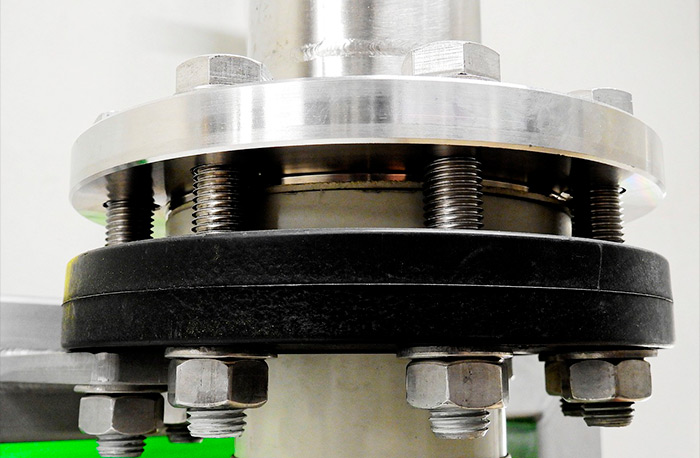
Flanges are often screwed or welded to the pipe ends and connected with bolts. A joint between the two flanges completely seals them to prevent water or gas leaks, while also protecting them against external foreign elements.
Thanks to their wide range of functions and applications, flanges are used in a wide variety of industrial and building sectors.
We can therefore safely say that flanges are a fundamental part for connecting internal systems in operations involving piping, valve and pump installations.
General flange composition
Flanges are made up of:
- The flange itself: This is the circular plate in which the holes and the connecting bolts are located.
- Neck: This is the part that connects to the pipe, however, not all flanges have a neck.
- Bolt diameter: This refers to the size of the holes into which the bolts are inserted.
- The face: Depending on the model, flanges come with different face types, with the most common being the raised or RF face, the flat or FF face, and the ring-type joint or RTJ.
Forged flange applications

Forged flanges are made in a variety of materials resistant to the weather and stress conditions they will have to withstand.
Given their resistance and load capacity, these flanges are used by several industries for both outdoor and indoor environments. They are very commonly found in parts used for solar plants, the petrochemical industry, medicine, the food sector, waste water treatment plants and many others.
How flanges are used depending on the temperature
Standards UNE-EN, ISO, ASME and AVK, among others, contain a number of specifications to be taken into consideration regarding the appropriate dimensions of flanges depending on the temperature they will have to withstand.
Carbon steel flanges are ideal for use in environments with moderate temperatures.
For more extreme temperatures, flanges in alloy steel must be used which are capable of withstanding these more extreme temperature and pressure conditions.
If the flanges will be in contact with corrosive liquids or gas, for example, it is advisable to use those made in metal alloys such as nickel, chrome and molybdenum.
Flange types
Flanges for connecting and welding
These flanges are ideal for low-pressure applications, thanks to their slightly wider internal diameter compared to the external diameter of the pipe. This means that they can be inserted easily from the end of the pipe to the place where they are to be welded, maintaining perfect adjustment the whole way.
Welding means that the flanges can be fixed in place at both the top and the bottom. They are also easy to use and fit, making them very cheap.
Socket weld flanges
Socket weld flanges are generally used on small-sized pipes in high-pressure environments.
To fix these flanges in place, the pipe is inserted into the socket until coming to the bushing or plug; the upper part is then lifted out slightly and welded. This means that the inside part of the pipe will remain perfectly smooth for the unobstructed circulation of gas or liquids.
Welded neck flanges
These are flanges fixed in place by welding the pipe to its neck, thereby transferring the flange stresses to the pipe and reducing the high-stress concentration at the bottom of the flange.
The main characteristic of this type of flange is its long cone-shaped neck, perfect for high-pressure applications.
The interior diameter of the flange must be machined to ensure that it matches the internal diameter of the pipes.
The conical centre of welded neck flanges transfers the pressure to the pipe, reinforcing it and providing the necessary strength to balance the lateral tilt.
Lap joint flanges
These flanges have the ability to swivel around the pipes and are often used with lapped pipes for simpler alignment with the holes and perfect coupling with the bolts.
Once the lapped pipe has been welded onto the pipe, the flange continues to turn freely. However, this has no effect on the bolt alignment.
These flanges are used in systems or applications requiring frequent dismantling, and when the pipes are in very hard materials.
They are generally made in steel, and their interior diameter is machined to ensure that it matches the collar.
Threaded flanges
This type of flanges can only be used on threaded pipes and can be assembled with no need for welding.

They are normally used with small-diameter, low-pressure pipes.
Blind flanges
Blind flanges are round plates with no centre holes used to seal off pipe ends, pressure tanks and valves. They are ideal for use on any size of standard pipe.
They are also used to check the pressure of liquid or gas in tubes or tanks, as well as enabling easy access to pipe interiors when required for repair. They are preferentially used for high pressure applications.
Types of flange faces
Flat face flanges
Flat face flanges have a contact surface on the same plane as the bolt frame.
Note that it is impossible for flat face flanges to couple with one another, as can however be achieved with raised face flanges.
Raised face flanges
Raised face flanges are frequently used in treatment plants and are easy to identify.
They get their name from the fact that the gasket surface is raised with respect to the bolt face.
These flanges enable the use of a high number of different joints. Their function is to concentrate more pressure in a smaller gasket area, increasing the ability of the joint to contain fluids.
RTJ flanges
RTJ flanges are typically used at high pressure (Class 600 or over and/or at temperatures higher than 427ºC).
They have a machined ring groove into which a steel gasket is inserted. The metal joint compresses when the bolts are torqued, so that the metal seal is compressed between the two flanges, deforming and creating direct contact between the metals.
RTJ flanges can come with a raised face with a machined neck; however, said face has no effect on its overall sealing capacity.
Tongue and groove flanges
This type of flange comes with two faces for coupling to one another. The tongue flange has a raised ring machined onto its face, while the other has a matching groove.
These flanges are typically used on valve caps and pump covers.
Tongue and groove flanges have the advantage of being self-aligning, hence acting as a reservoir for the adhesive. In addition, the scarf joint keeps the loading axis perfectly aligned.
It is important to note that RTJ and T&G flanges must not, under any circumstances, be installed together, given the differences in their contact surfaces; it is also impossible to achieve any kind of joint between flanges with different faces.
How to read the flange identification
Carbon and stainless steel flanges are marked according to the requirements of the ASME B 16.5 standard. This is the flange standard most widely used worldwide.
This standard includes both forged and cast flanges and stipulates the materials, marking, dimensions, working pressures, tolerances and flange tests.
It also describes each type of flange measurements, from 1/2” to 24″, with their pressure classes 150, 300, 400, 600, 900 and 1500; and from 1/2” to 12” in class 2500.

We can say that the fundamental characteristics of flange identification are:
- The manufacturer’s logo.
- The standard used to make the flange.
- The material designated according to the ASTM, and their heat treatment.
- The nominal diameter and pressure range of the flange.
- Their face type.
- The identification number assigned by the manufacturer.
- For welded neck or socket weld flanges, the nominal thickness of the pipe to which they must be welded is indicated.
DIN, ANSI and JIS reference table
The PN (DIN or Deutsches Institut für Normung standard), LB (pounds) or class (ANSI or American National Standards Institute standard) and K (JIS or Japanese Industrial Standards) indicators show the nominal pressure for valves, pipes and their accessories.
Each system differs according to the temperature taken as a reference, and the material from which the flange is made; for example, in DIN this corresponds to 120ºC, but in ANSI it corresponds to 425.5ºC.
In the case of European systems like DIN, EN, BS, ISO, and of the Chinese GB standard, they use the term PN. This is a pressure range based on the bar unit: PN2.5, PN6, PN10, PN16, PN25, PN40, PN63, PN100, PN160, PN250, PN320 and PN400.
However, in the American system they use the term Class, often expressed as class150, 150LB or 150#, representing the pressure range of the valve or tube. Said value is the result of calculating the joint pressure of a certain metal and the temperature according to the ANSI B16.34 standard.
In Japan they use the K unit when indicating pressure levels. Note that there is no strict correspondence between the degree of pressure and the nominal pressure due to difference in their reference temperature.
The following table reflects the approximate conversions between each of these systems; however, we must point out that, not being values, an exact conversion is impossible.
Note that the last column of this table refers to the equivalence expressed in Megapascals (Mpa), i.e. the pressure unit used by the International Units System.
| DIN (PN) | ANSI (LB) | JIS (K) | Mpa |
| 20 | 150 | 10 | 2 |
| 50 | 300 | 20 | 5 |
| 64 | 400 | 30 | 6.8 |
| 100 | 600 | 40 | 11 |
| – | 800 | – | 13 |
| 150 | 900 | 63 | 15 |
| 250 | 1500 | 100 | 26 |
| – | 2000 | – | 33.7 |
| 420 | 2500 | – | 42 |
Thanks to the above information, you now have a complete and extensive idea of flanges, their characteristics and uses according to the temperature and pressure of the environment in which they are applied.
Lastly, please note that at Couth we offer you an industrial marking service used on flanges for their identification. For more information, please don’t hesitate to contact us.


